A heavy mineral sands deposit containing chromite, garnet, zircon and titanium bearing minerals.
Initial studies identified a problematic magnetic susceptibility overlap between the titanium bearing minerals and the chromite. For this reason, early test work had defined an overall saleable chromite recovery limit ranging from 60–70%. The following case study focuses on the process development testwork specifically targeted at increasing chromite recovery without compromising finished product quality.
Gravity concentration was carried out utilizing a combination spiral and Gulin® density separator circuit, for optimal preconcentration, followed by an attrition scrubbing stage. Due to the specific assemblage, using magnetic separation alone would produce a combination product of magnetite, titanium-bearing minerals, chromite and garnet. For this reason, the use of Wet high-intensity electromagnetic separators was ruled out early. After drying, high tension roll separation was used to create a conductor fraction containing mainly magnetite, titanium bearing minerals and chromite.

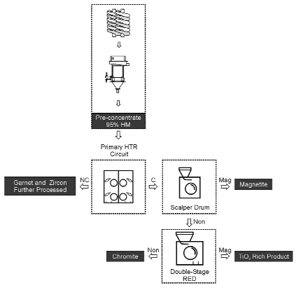
Extensive small-scale testing was carried out to determine the best magnetic separation route for increasing chromite recoveries, resulting in a large number of rare-earth drum and rare-earth roll flowsheet configurations being evaluated. Ultimately, a multi-stage scalper/rare-earth drum circuit was defined to effectively scalp magnetite and increase chromite recovery approximately 20% over the previous work. The mid-range intensity of the drum allowed for improved selectivity in the chromite and ilmenite separation, while also allowing higher rate processing than the rare-earth roll.
The first drum pass is used solely to remove the magnetite fraction. The second two rare-earth drum stages, arranged in a middling-retreat configuration, produce the chromite and titanium-rich products. Unique to this chromite magnetic circuit design is that the chromite product is comprised of the non-magnetic streams from the second and third rare-earth drum stages. Given this fact, it is important to note that the preceding high tension roll electrostatic step is critical to avoid possible non-conductor contamination of the chromite product. The basic flowsheet is illustrated in Figure 6.
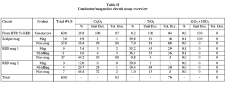
Assays from this portion of the circuit are overviewed in Table II.

The HT conductor fraction contained 87% of the head feed Cr2O3 units, and of the head feed, 82% of the Cr2O3 was recoverare-earth drum in this rare-earth drum circuit versus the 60–70% Cr2O3 recovery by prior test work. Of the recoverable Cr2O3 units in the magnetic separation stage alone, the combined Cr2O3 recovery was 95.9% with an average product quality of 44.5% Cr2O3 (95.2% chromite).
A Wet high-intensity electromagnetic separators was not recommended for this application for the following reasons:
- The Wet high-intensity electromagnetic separators was tested previously and resulted in low chrome recovery
- The Wet high-intensity electromagnetic separators removed the magnetic non-conductors along with the magnetic conductors so an electrostatic step would still be requirare-earth drum
- The use of a Wet high-intensity electromagnetic separators would not have saved in drying costs.

